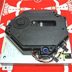
2007-01-06
|
A little pice of advice, (or WARNING if you like.)
I don't care if this is a laser product or
not, or if you go blind or maim yourself in any kind of horrible
way. Only a very 'skilled' individual would be 'lucky' enough
to injure himself by peeking into the lens with the power on,
holding still untill total blindness occures.
What I do care about is that the GD-ROM drive is a sensitive pice
of equipment. If you crack, scratch, move, drop
or bend certain details inside the
drve, the drive could stop working properly.
|
I hope this sign
is well in your way...
This page applies
to all maintnance and/or repair to Sega's GD-ROM drive.
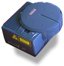
Cleaning
the GD-ROM drive inside should be made with utmost care and consideration
for the drive's internal parts. It is a simple but delicate construction
which isn't too different from any PC or other electronic home appliances.
But, what is important to remember is that the GD-ROM drive is a very
exclusive device by itself, and regarding spare parts. If you break
it, you must find another drive.
With that said I'll get into the details of how to disassemble, clean,
and reassemble the unit. I hope I don't have to remind you to thoroughly
wash your hands in soap before working. If we wouldn't appreciate hygien
we wouldn't consider cleaning our GD-ROM drive.
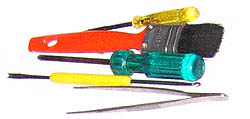
Tools you need:
|
-
A paintbrush (dusting)
- tweezers (positioning details)
- small slotted screwdriver (support)
- a little hook (pulling / guiding leads)
- two sizes of phillips head screwdriver
- a steady table with some damping
|
|
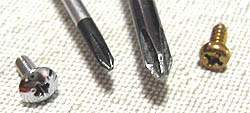 |
Your
simplest and most basic tool is the screwdriver. They are made
in different shapes and sizes for a reason - never ever challenge
the screw! (You don' eat soup with a fork either, or cut meat
with a spoon, do you?)
|
Things
you should know:
There are several types of screws in the GD-ROM drive, they are to be
kept appart from each other, and used only in their designated place.
The threading is different between each type, putting a wrong type in
a metal threading will damage the threadings of both the screw and the
screw-hole, *and* it will damage the new screw which you will try to
screw into that threading.
I've devided all screws into groups. Refering to an certain screw type
will from now be very easy. Open a new browser window or save the picture
to your hard drive, and have it next to your reading for quick referens.
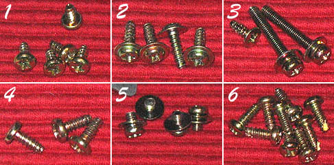
Group
1
Holds two metal plates together, introduced in sectiion 'DISASSEMBLING
D'. |
Group 2
Holds the 'SCSI connector-pcb' in place, section 'DISASSEMBLING
F'. |
Group
3
These screws attach the >fan retainer<
to the fan. The smaller flat-head screw holds the ''lock-tap retainer''
in place from within the upper lid, with one group-1 screw. |
Group 4
These secure the motor & laser-unit 'nest' to its metal base.
'DISASSEMBLING Q'. |
Group 5
Four fine threaded M3 screws with permanently attached spring washers,
are used in metal to metal parts spread over a few sections. |
Group
6
Five if these screws hold the main drive case together, two hold
the security de-activating mechanism on the upper plastic caseing,
and two mount the fan retainer to the lower plastic casing. |
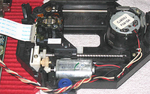
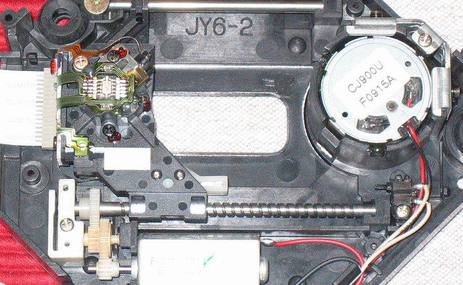
DISASSEMBLING
Green
arrows mark out general screw positions. Orange arrows call
for closer attention or point out areas which need extra caution.
DISASSEMBLING
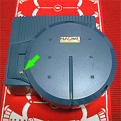
A
Remove the little M3 phillips (or pozi) screw marked with the green
arrow in the picture. You could leave it just as well, but since
we are going to remove other details later, we need the lid open.
This screw
has been omitted in the screw-group overview with purpose. It's
a little M3 thread which sometimes is missing in used drives.
|
|
|
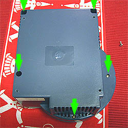
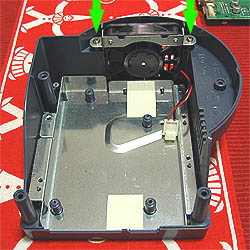
DISASSEMBLING
B
Turn the drive upside down and remove the five screws (group-6)
marked with green arrows.
|
|
|
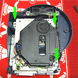
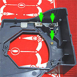
DISASSEMBLING
C
Turn the drive back to upside and remove the three screws marked
with green arrows.
The upper left screw is a group-6, the other two on the right
are group-5 screws. Then try to evenly lift up the motor/laser
unit holding it by its sides. Rock gently if you have to.
|
|
|
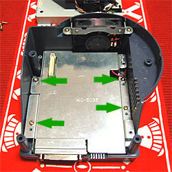
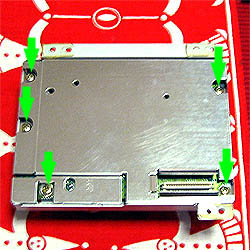
DISASSEMBLING
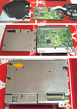
D
Remove the four screws marked with green arrows. The upper left
screw is a group-2 screw. The remaining three are group-6.
This metal plate should be quite loose once the screws are gone.
|
|
|
DISASSEMBLING
E
Turn the drive 90 degress counter clockwise and lift up the metal
plate revealing the SCSI connector-pcb. But be carefull not to
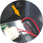
lift it all the way. You must first disconnect the fan from the
board.
This moment can be quite tricky, so watch what you are doing.
Use your nails or a slotted screwdriver to push away the nylon
connector.
|
|
|
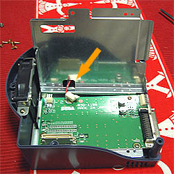
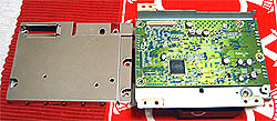
DISASSEMBLING
F
Turn the drive 90 degrees clockwise, back as it was. (Or leave
it as you feel most comfortable, I'm just turning it to get a
good angle for my camera.)
Loosen the three group-2 screws, and the one group-5 screw marked
with an orange arrow, loosening the pcb retainer.
Remove the pcb.
|
|
DISASSEMBLING
G
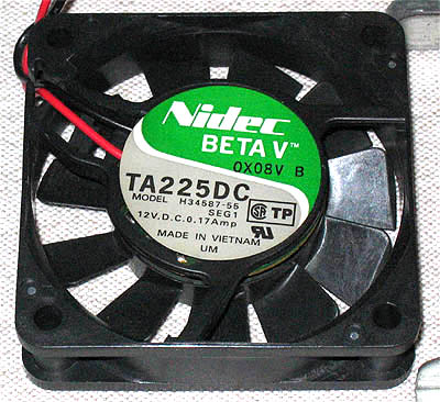
The two screws attaching the fan to the plastic mold are group-6.
Remove them.
At this point you would want to get closer to your kitchen sink,
and have your brush ready. Gently blow away from you, into the
sink as you lift the fan out of its place. Leave the fan in the
sink while softly blowing air and removing dust sediments from
the casing.
The fan is cheap type >>
look <<
A square 60 x 10 (mm)
|
|
|
DISASSEMBLING
H
After you're done parting the fan from its retainer, put the fan
into hot water with a dash of household detergent. Leave it to
soak.
Now let's focus on the top mold of the drive casing. The security
de-activating mechanism is fastened by two group-6 screws. The
mech is a two-piece unit which is joined by two more screws locked
with 'lock-tite'. Leave them. Wash the mech as it is. (Mind the
spring!)
|
|
|
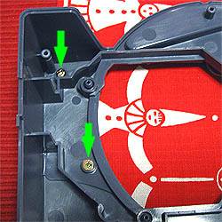
DISASSEMBLING
I
Turning the top mold a 180 degrees...
... the upper screw is a group-6, and the bottom screw (also in
picture H, not mentioned) is group-3, the small one in that group.
Removing these will detach the smaller section of the top casing,
I call it the 'lock-tap retainer' as it retains the lid lock-tap.
|
|
|
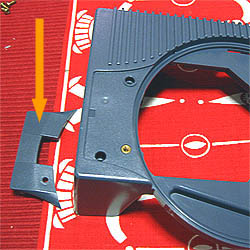
DISASSEMBLING
J
Look how nicely it comes off. You almost don't need this part...
Now it's time for a good bath! Throw all plastics into the bubbles
and give them a good scrub, ( ! ) with a soft sponge that is.
Don't use any kinds of abrasives or polish. Just plain sponge
and nylon brush will do the job. Remember not to mix metal parts
with plastics as metal can scratch the plastic parts.
|
|
|
DISASSEMBLING
K
Notice the fragile switch at the bottom right? Blow away all dust
gathered there. If there's plenty, use the brush gently.
Also at this point you can clean away dust on the outer surfaces
with your brush. Make sure you blow in the proper direction, down
the sink preferably. The inside of the laser-unit's 'nest' is
seemingly clean as it's kept well isolated from the air flow in
the rest of the casing during operating.
|
|
|
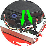
NOTE!
You will need to bend the two retainers upwards and slide the
lead harness outwards. Both of the retainers must let go of the
leads for you to be able to lift the motor-laser unit out of its
'nest'.
|
|
|
DISASSEMBLING
L
'Laser upside down'! This moment is best performed holding the
drive in one hand, minding not touching the lens, and working
with the other. You must pay close attention to the laser unit
not falling out, it is loose!
All screws here are group-1 except the upper left one which is
a group-5 screw. This piece of thin metal shield can be tricky
to remove even once the screws are out. Force it evenly starting
with corners.
|
|
|
DISASSEMBLING
M
As you can see it's not impossible to remove the shield. Just
pull upwards at the corners. Do not scew or slide sideways, components
may get in the way.
|
|
|
DISASSEMBLING
O
|
|
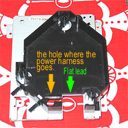
After removing
the shield, flippig the assembly back upside again, you will now
remove the laser unit from it's 'nest'. You have already detached
the two cable clamps securing the power harness (Note! section
'K') so all you need to do is carefully guide the flat lead, and
the power harness, out of the 'nest'.
Holding the metal casing with your left hand, start by lifting
the laser unit up with your right, at the same time as you move
slightly to the right / backwards, keeping the orientation where
the cables and flat-lead are. Do not pull or jerk anything! Gently
and slowly then twist north, guiding the power harness out of
its round hole. The power harness is connected to the control-pcb
by small connectors, but it's infact easier to not disconnect
these, just let it all hang, guiding the harness out of the hole.
- You will know once you're there.
|
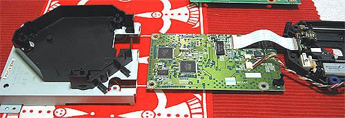 Note: The orientation
and position of the modules pictured above is correct except for the
laser-unit (rightmost) is on its back due to 'opening' like a clamshell.
The pcb goes straight under the metal base, with the laser unit 'closing'
from above, ending up in its plastic 'nest'.
Note: The orientation
and position of the modules pictured above is correct except for the
laser-unit (rightmost) is on its back due to 'opening' like a clamshell.
The pcb goes straight under the metal base, with the laser unit 'closing'
from above, ending up in its plastic 'nest'.
|
More
pictures (high resolution)
|
|
|
|
DISASSEMBLING
P
Details explained. To trick the leads to come out of their windings
is the biggest challenge.
The flat cable is quite easy, it's the power harness that needs
guiding and pushing in the desired direction, and over the little
tab that prevents the power harness from accidently falling out
of its place.
|
|
|
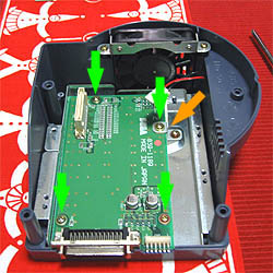
DISASSEMBLING
Q
Flipping the lot once more, all three screws in the picture are
group-4. The orange arrow points at the little tab which hooks
in place once the plastic 'nest' is aligned correctly. There are
several notches which retain the 'nest' steady to the metal base.
When reassembling make sure the plastic pins are well placed in
all notches.
That square little 'pinky' in the middle is best left alone. It's
glued to the metal and is a cooling transmitter for an IC located
on the drive's 'controller pcb'.
|
|
|
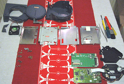
DISASSEMBLED
R
|
|
Here's
your drive boy. Now put it together! You know how?
|
 ... well, you'd better.
Or get a new drive from Sega.
... well, you'd better.
Or get a new drive from Sega.
REASSEMBLING
REASSEMBLING
A
Let's start by making sure all our plastics are nicely dry. I use
put them ontop of my vacuum for 15 minutes where the warm exhaust
evaporates almost every drop of water. I often help a bit by manually
blowing air into screw holes
and other hard to reach places. Use a tooth pick to reach deeper
and then touch your lips with the pick to check for moist. |
|
REASSEMBLING
B
First plate in place. You should wash your metal parts with a
sponge to make them nice and shiny. They dry pretty quickly since
they are very simple.
Remember to check that all notches are filled / occupied by the
plastic pins beneath. Make sure that the plates lay flat and snapped
into position. Otherwise you will not be able to close the thing
shut at the end. |
|
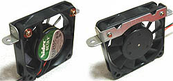 After a bath and
some scrubbing your fan should dry in a half an hour above the vaccum.
Give it an occasional blow under its blades to force the water out.
Check its rotation resistance, it shoud spin easilly. Otherwise swap
it for a new one. Get Papst or whatever.
After a bath and
some scrubbing your fan should dry in a half an hour above the vaccum.
Give it an occasional blow under its blades to force the water out.
Check its rotation resistance, it shoud spin easilly. Otherwise swap
it for a new one. Get Papst or whatever.
REASSEMBLING
C
Reassembling is very much the reversed procedure of the disassembling.
However, when reassembling the drive we must pay close attention
to how the leads are placed, so that there will not be any jammed,
which could ultimatly cause a short.
We are already familliar with the screws, the retainer is attached
to the fan with the two group-3 (long ones), and mounted inside
with group-6. Air flow direction should be 'out'. |
|
|
NOTE!
Make sure that the fan leads do not get in the way of the blades,
squeezed between the fan and the wall, or cut by metal egdes!
Leads should exit at the lower right corner.
|
|
|
REASSEMBLING
D
Group-2 at the greens, and group-5 on the orange one. And don't
forget the retainer.
|
|
|
REASSEMBLING
E
This is somewhat of a critical
moment.
The leads are just long enough to pass through the hole and connect
to the pcb.
The tweezers come well in handy.
|
|
|
REASSEMBLING
F
After you''ve managed to encapsulate the SCSI connector-pcb, with
the fan leads safely attached and not jamed, it's time for securing
the plate with four screws.
Upper left is a group-2, the other three are group-6.
|
|
|
REASSEMBLING
G
Now it's time for the laser unit to go back into its 'nest'. We
already know our metal plates, and where they go. We take the
plastic part and gently let it find its place on the metal surface.
You see the notches to align them with the pins, and make sure
the little hook (orange arrow) is inserted and that all snaps
into place. You can easilly test the stability by then trying
to move the 'nest' sideways. It should be quite stuck. Secure
with all three group-4 screws.
|
|
|
REASSEMBLING
H
You remember this sequence, yes? Alright, but it's in reverse
order now.
You start by flipping the 'nest' module to upside position. Grabbing
it by the metal sides with your left hand, at the same time holding
the laser-unit in your right, try to manouver the power harness
first sideways into its hole and into position. I remember having
an easiser time reinstalling the laser unit, then removing it.
Afterwards the flat lead pretty much places itself.
Then flip the lot again, securing the pcb and shield plate to
the metal base plate with four group-1, and one group-5 (upper
left, bottom picture).
|
 Note that the
the assembly in the bottom picture is rotated 180 degrees contra
the modules in the middle picture.
Note that the
the assembly in the bottom picture is rotated 180 degrees contra
the modules in the middle picture. |
|
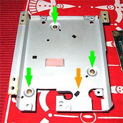
NOTE!
Flipping the lot a last time, will leave you with the task of
attaching the laser & motor unit's power harness under the
clamps marked with green arrows. Simply slide them under as the
clamps are snap-in designed for quick assembling.
|
|
|
REASSEMBLING
I
Beautiful! You're almost there!
More importantly, check that the harness goes loosly out from
the 'nest' and then leads into the 'nest' again, as showed in
the picture.
By now your plastics and metals must be dry, so let's continue
where we left off at 'Reassembling 'F', and install our laser
module.
|
|
|
REASSEMBLING
J
One upper left Group-6, and two group-5 screws secure the laser
unit in place. What's left now is to put on the top casing, and
the work will be done! Which reminds me that the lens could also
need some cleaning.
For that there are commercial cleaners which will do the job perfectly.
The lens is always accessible just by opening the lid any time
between game swapping, so cleaning it can be done any time.
|
|
|
REASSEMBLING
K
Oh, we almost forgot the lock-tap retainer, ...
|
|
|
REASSEMBLING
L
Upper left - group-6, the bottom one - group-3 'short screw'.
|
|
|
REASSEMBLING
M
The upper two screws are group-6, and the last one at the middle
we already accounted for.
I think it's time to put on the lid.
|
|
|
REASSEMBLING
N
Only five group-6 left to secure.
|
|
|
REASSEMBLING
O
We don't even need to use the M3 lid-lock screw. Let's just put
the lid on, it holds in place quite nicely just turning it 5 degrees
counter clockwise.
|
|
And
there you have it! A GD-ROM drive clean as a whistle!
<< Back to top
|